AWS Transit Gateway 概述和最佳实战
介绍
让我们使用 AWS Trasit Gateway 连接到 AWS 网络服务。
有以下四种情况。 还描述了每个的设置过程。
- ① 连接中转网关和VPC
- ②尝试使用 VPN 连接 Transit Gateway 和本地环境
- ③尝试不同VPC之间的连接
- ④尝试连接其他地域的VPC
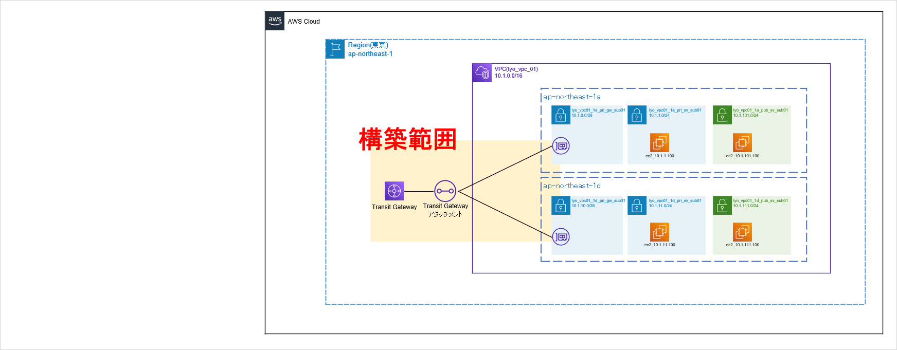


从那时起,我们将构建上面的步骤1到4。
① 连接中转网关和VPC
构成
首先,构建 Transit Gateway 并将其连接到 VPC。 之后,我们将连接到本地或连接到另一个VPC或区域,但这只是初步准备。

此外,虽然 Transit Gateway 连接的子网是“tyo_vpc01_1a_pri_gw_sub01”和“tyo_vpc01_1d_pri_gw_sub01”,但不会在这些子网中创建实例。 这将是 Transit Gateway 的专用子网。 原因是因为以下建议。
*以下 AWS官方博客 摘自
问:我想提供一个更具体的示例,并解释在附加 VPC 时指定的子网作为仅附加子网的必要性。 您说它会影响该子网内 EC2 实例的路由,但它会产生什么样的影响呢? 我想了解更多相关信息。
答:如果 EC2 实例与具有传输网关 (TGW) 连接的实例位于同一子网中,则该 EC2 实例引用与 TGW 相同的路由表。
例如,如果您在具有用于 VPC 内联审核的 TGW ENI 的子网上安装 EC2 实例,则该 EC2 实例将始终被吸入中间盒 ENI 中以进行内联审核,从而无法创建该实例所需的路由表。 EC2 实例将会消失。 为了防止这种情况发生,我们建议为 TGW 创建专用子网。https://aws.amazon.com/jp/blogs/news/webinar-bb-aws-transit-gateway-2019/
设定方法
现在让我们进入设置。
首先,从“VPC”中选择“Transit Gateway”,然后按“创建 Transit Gateway”。

输入任何名称标签并输入“亚马逊自治系统编号 (ASN)”。 这将是以后配置 BGP 时的 AS 编号。 其他设置为默认值。 输入完成后,按“创建中转网关”按钮。

验证状态是否变为可用。

接下来,将 Transit Gateway 连接到子网。 首先,选择“Transit Gateway 附件”并按“创建 Transit Gateway 附件”。

在 Transit Gateway 连接屏幕上输入以下信息。

验证状态是否变为可用。

这就是设置的全部内容。 在下一页上,使用 VPN 连接 Transit Gateway 和本地环境。
②尝试通过 VPN 连接 Transit Gateway 和本地环境
构成
接下来,使用您之前创建的 Transit Gateway 将本地连接到 VPN。
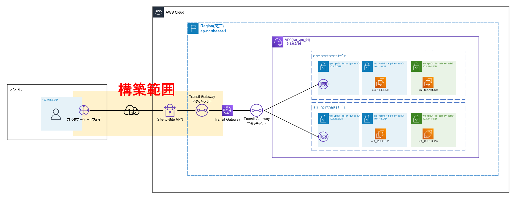
在施工过程中,我们将完成以下工作:
- 创建客户网关(创建本地VPN设备的信息)
- 从 Site-to-Site VPN 下载本地 VPN 设备的示例配置
- 构建本地 VPN 设备
- 将本地路由添加到 VPC 路由表
- 将客户网关连接到您刚刚构建的 Transit Gateway
设定方法
首先,创建客户网关。 客户网关注册本地VPN设备的VPN终结IP地址。 我们的环境使用 Fortigate。


验证状态是否变为可用。

接下来,将您之前创建的客户网关附加到 Transit Gateway。


验证状态是否变为可用。

这就是AWS端的所有设置。 最后,当您查看站点到站点 VPN 时,会看到一个带有 Transit Gateway 和附加客户网关的设置,因此选择它并“下载设置”。 此设置是本地 VPN 设备的示例配置。


下载示例配置后,您需要将其放入实际机器中,但本文中我们将省略这一点。
此外,如果本地 VPN 设备可以毫无问题地设置 VPN 和 BGP,则将与 AWS 建立连接,状态将显示为“Up”,详细信息将显示为“X BGP ROUTERS”,如下所示如下所示。

我还将附上本地路由表以供参考。 *您可以看到 BGP 正在学习 VPC (tyo_vpc_01) 的 10.1.0.0/16。 (12号线路线)
FGT60D # get router info routing-table all

Routing table for VRF=0
Codes: K - kernel, C - connected, S - static, R - RIP, B - BGP
       O - OSPF, IA - OSPF inter area
       N1 - OSPF NSSA external type 1, N2 - OSPF NSSA external type 2
       E1 - OSPF external type 1, E2 - OSPF external type 2
       i - IS-IS, L1 - IS-IS level-1, L2 - IS-IS level-2, ia - IS-IS inter area
       * - candidate default

S*      0.0.0.0/0 [5/0] via 61.26.71.129, wan1
B       10.1.0.0/16 [20/100] via 169.254.157.109, P1_AWS-vpn2-T1, 00:01:30
C       61.26.71.128/25 is directly connected, wan1
C       169.254.157.108/30 is directly connected, P1_AWS-vpn2-T1
C       169.254.157.110/32 is directly connected, P1_AWS-vpn2-T1
C       169.254.181.80/30 is directly connected, P1_AWS-vpn2-T2
C       169.254.181.82/32 is directly connected, P1_AWS-vpn2-T2
C       192.168.0.0/24 is directly connected, internal1


FGT60D #
最后,在应用于VPC的路由表中配置本地路由。

将本地网络路由到目标 Transit Gateway。

验证配置的路由现在是否处于活动状态。

这样就通过 Transit Gateway 完成了本地与 AWS 之间的连接。 确认从本地PC到EC2实例的traceroute成功。 (我假设没有显示 2 跳,因为它们是 VPN 隧道)
C:\Users\ktrwa>tracert -d 10.1.11.100

10.1.11.100 へのルートをトレースしています。経由するホップ数は最大 30 です

  1     4 ms     8 ms     8 ms  192.168.0.254
  2     *        *        *     要求がタイムアウトしました。
  3    12 ms    19 ms    15 ms  10.1.11.100

トレースを完了しました。

C:\Users\ktrwa>
这就是 Transit Gateway VPN 连接的全部内容。 在下一页中,我们将在不同的 VPC 之间进行连接。
③尝试不同VPC之间的连接
构成
接下来,通过 Transit Gateway 连接两个 VPC。
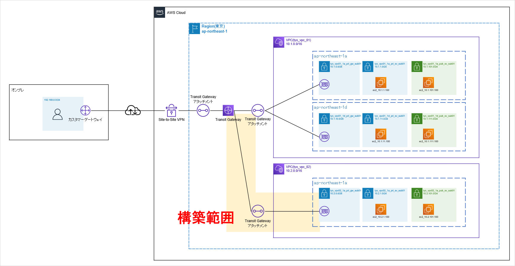
在施工过程中,我们将完成以下工作:
- 将 VPC (tyo_vpc_02) 连接到已创建的 Transit Gateway
- 将本地路由添加到VPC(tyo_vpc_02)的路由表中
设定方法

验证状态是否变为可用。

接下来,将本地路由添加到 tyo_vpc_02 的路由表中,该路由表将成为连接目标。


验证添加的路由状态是否为Active。

如果查看本地路由表,您可以看到 tyo_vpc_02 (10.2.0.0/16) 网络是使用 BGP 获知的。 (见第 13 行)
FGT60D # get router info routing-table all

Routing table for VRF=0
Codes: K - kernel, C - connected, S - static, R - RIP, B - BGP
       O - OSPF, IA - OSPF inter area
       N1 - OSPF NSSA external type 1, N2 - OSPF NSSA external type 2
       E1 - OSPF external type 1, E2 - OSPF external type 2
       i - IS-IS, L1 - IS-IS level-1, L2 - IS-IS level-2, ia - IS-IS inter area
       * - candidate default

S*      0.0.0.0/0 [5/0] via 61.26.71.129, wan1
B       10.1.0.0/16 [20/100] via 169.254.157.109, P1_AWS-vpn2-T1, 09:18:42
B       10.2.0.0/16 [20/100] via 169.254.157.109, P1_AWS-vpn2-T1, 00:06:26
C       61.26.71.128/25 is directly connected, wan1
C       169.254.157.108/30 is directly connected, P1_AWS-vpn2-T1
C       169.254.157.110/32 is directly connected, P1_AWS-vpn2-T1
C       169.254.181.80/30 is directly connected, P1_AWS-vpn2-T2
C       169.254.181.82/32 is directly connected, P1_AWS-vpn2-T2
C       192.168.0.0/24 is directly connected, internal1


FGT60D #
我们还确认可以从本地 PC 与 tyo_vpc_02 (10.2.0.0/16) 中存在的 EC2 实例进行通信。
C:\Users\ktrwa>tracert -d 10.2.1.100

10.2.1.100 へのルートをトレースしています。経由するホップ数は最大 30 です

  1     3 ms     6 ms     5 ms  192.168.0.254
  2     *        *        *     要求がタイムアウトしました。
  3    15 ms    13 ms    18 ms  10.2.1.100

トレースを完了しました。

C:\Users\ktrwa>
至此,不同VPC之间的连接就完成了。 接下来,连接到另一个区域。
③尝试不同VPC之间的连接
构成
接下来,通过 Transit Gateway 连接两个 VPC。
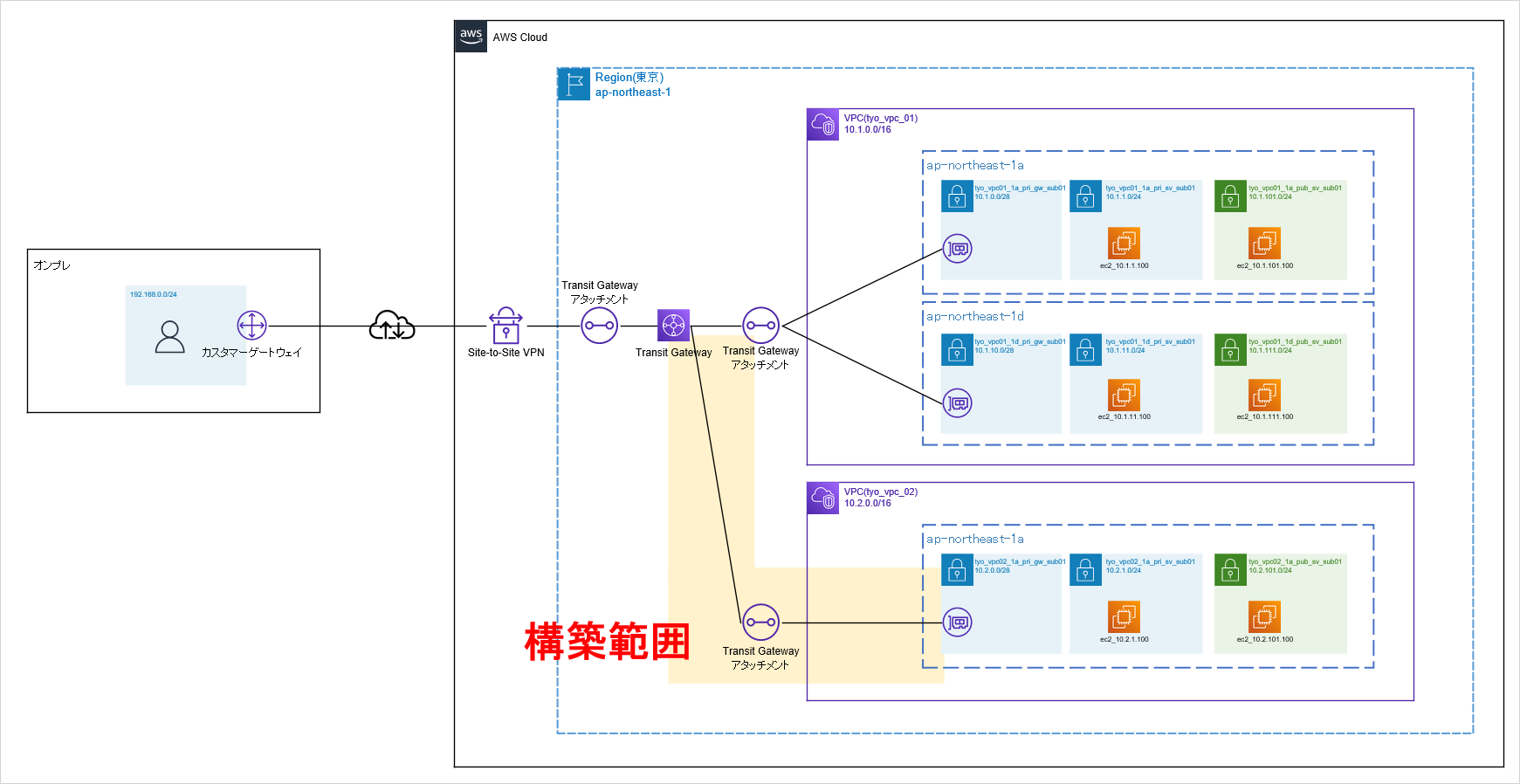
在施工过程中,我们将完成以下工作:
- 将 VPC (tyo_vpc_02) 连接到已创建的 Transit Gateway
- 将本地路由添加到VPC(tyo_vpc_02)的路由表中
设定方法
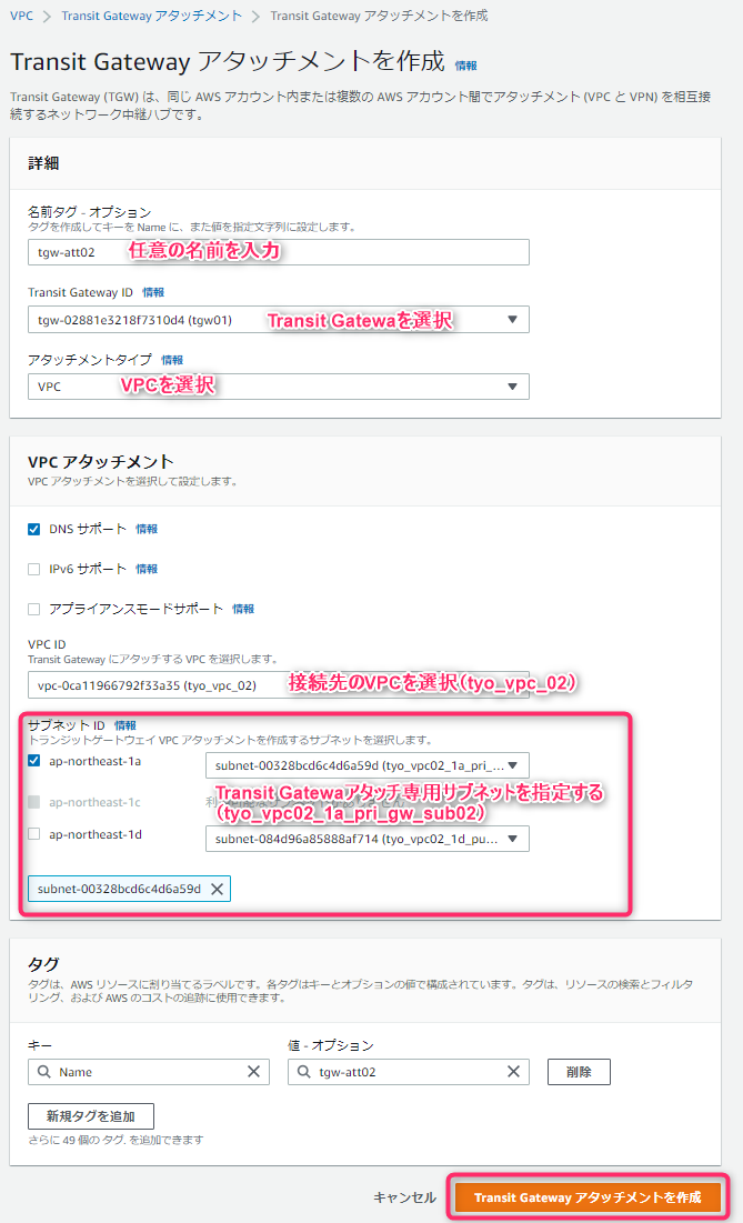
验证状态是否变为可用。

接下来,将本地路由添加到 tyo_vpc_02 的路由表中,该路由表将成为连接目标。
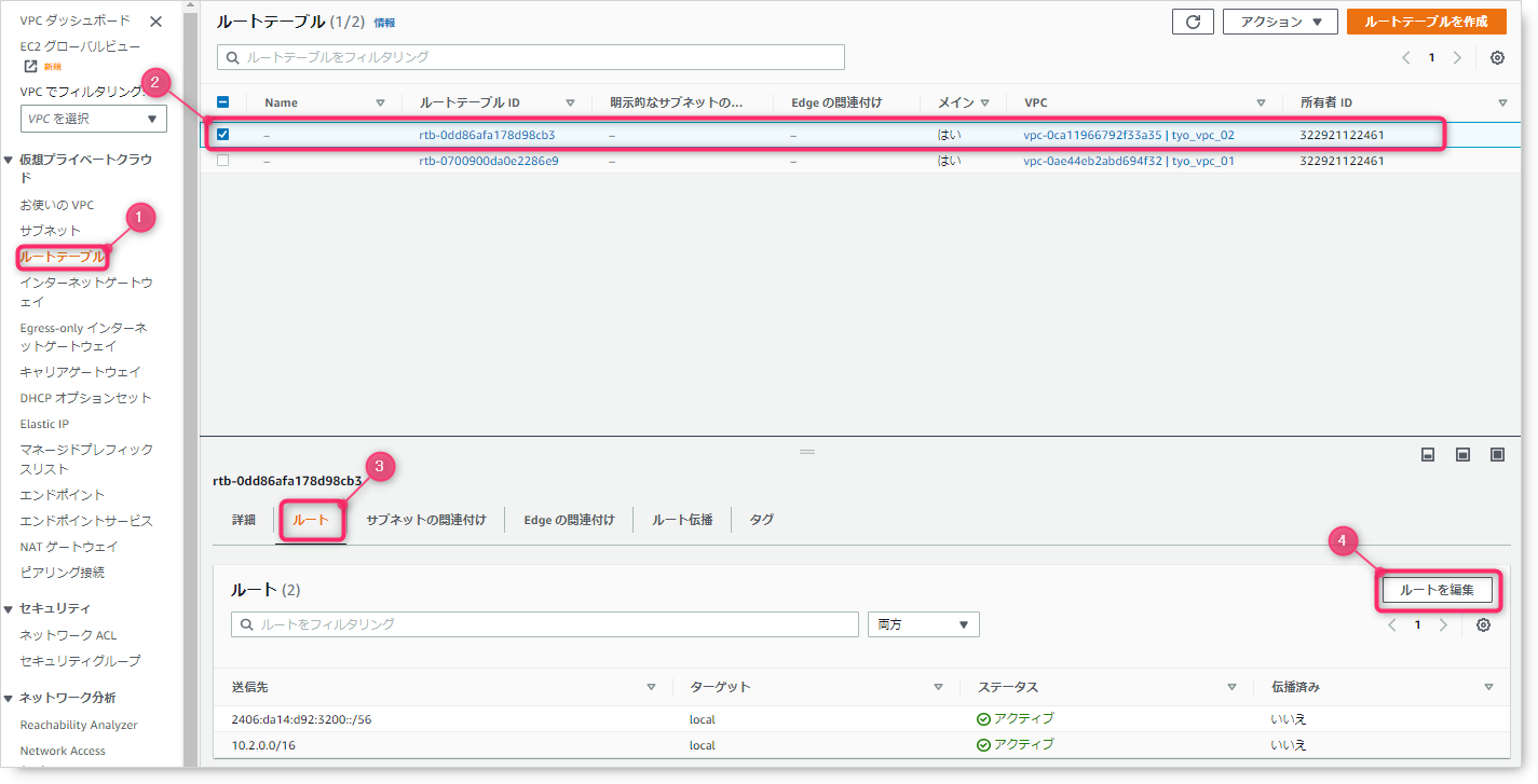

验证添加的路由状态是否为Active。
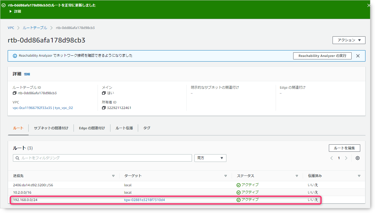
如果查看本地路由表,您可以看到 tyo_vpc_02 (10.2.0.0/16) 网络是使用 BGP 获知的。 (见第 13 行)
FGT60D # get router info routing-table all

Routing table for VRF=0
Codes: K - kernel, C - connected, S - static, R - RIP, B - BGP
       O - OSPF, IA - OSPF inter area
       N1 - OSPF NSSA external type 1, N2 - OSPF NSSA external type 2
       E1 - OSPF external type 1, E2 - OSPF external type 2
       i - IS-IS, L1 - IS-IS level-1, L2 - IS-IS level-2, ia - IS-IS inter area
       * - candidate default

S*      0.0.0.0/0 [5/0] via 61.26.71.129, wan1
B       10.1.0.0/16 [20/100] via 169.254.157.109, P1_AWS-vpn2-T1, 09:18:42
B       10.2.0.0/16 [20/100] via 169.254.157.109, P1_AWS-vpn2-T1, 00:06:26
C       61.26.71.128/25 is directly connected, wan1
C       169.254.157.108/30 is directly connected, P1_AWS-vpn2-T1
C       169.254.157.110/32 is directly connected, P1_AWS-vpn2-T1
C       169.254.181.80/30 is directly connected, P1_AWS-vpn2-T2
C       169.254.181.82/32 is directly connected, P1_AWS-vpn2-T2
C       192.168.0.0/24 is directly connected, internal1


FGT60D #
我们还确认可以从本地 PC 与 tyo_vpc_02 (10.2.0.0/16) 中存在的 EC2 实例进行通信。
C:\Users\ktrwa>tracert -d 10.2.1.100

10.2.1.100 へのルートをトレースしています。経由するホップ数は最大 30 です

  1     3 ms     6 ms     5 ms  192.168.0.254
  2     *        *        *     要求がタイムアウトしました。
  3    15 ms    13 ms    18 ms  10.2.1.100

トレースを完了しました。

C:\Users\ktrwa>
至此,不同VPC之间的连接就完成了。 接下来,连接到另一个区域。
④尝试连接其他地域的VPC
构成
最后连接其他地域的VPC。
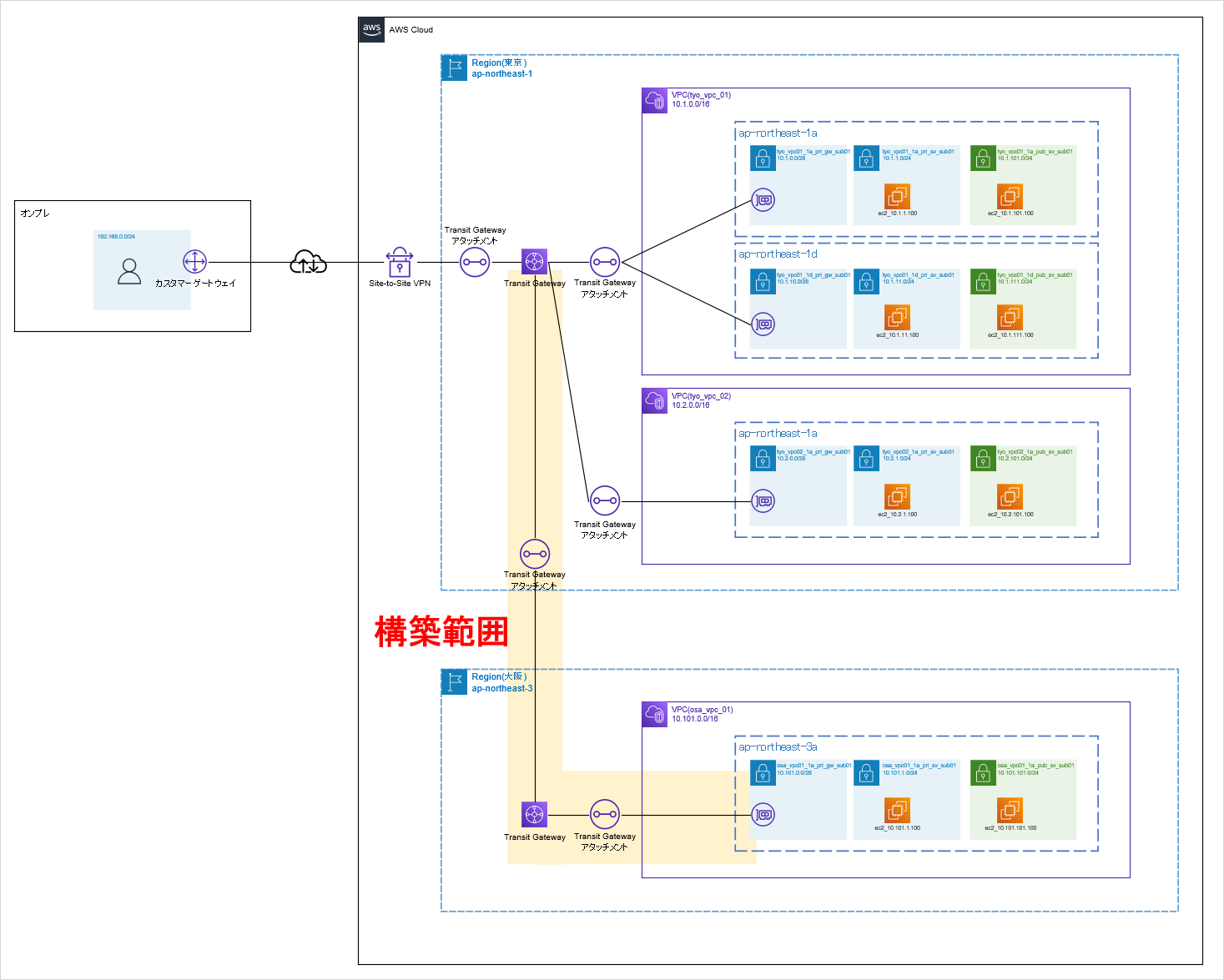
在施工过程中,我们将完成以下工作:
- 在大阪地区创建一个要连接的 Transit Gateway。
- 在大阪区域连接中转网关和 VPC (osa_vpc_01)
- 从东京地区的 Transit Gateway 向大阪地区的 Transit Gateway 发出对等互连请求
设定方法
构建时,首先切换到连接目的地的大阪地区,从“Transit Gateway”创建Transit Gateway。


接下来,切换到东京区域并与您之前创建的大阪区域中的 Transit Gateway 对等。


状态为待接受。 (如果您在大阪地区接受请求,则可以使用)

接下来,返回大阪地区并接受东京地区的Transit Gateway附件。


验证状态是否变为可用。

至此,东京地区和大阪地区已使用 Transit Gateway 建立对等关系。 剩下要做的唯一一件事就是设置路由。 执行以下路由设置。
- 将本地路由添加到大阪地区VPC路由表
- 将本地路由添加到大阪地区的 Transit Gateway 路由表
- 将大阪地区的 VPC 路由添加到东京地区的 Transit Gateway 路由表
首先,我们设置大阪地区的路由。


接下来,将本地路由添加到 Transit Gateway 路由表中。


接下来,切换到东京区域,并在 Transit Gateway 路由表中添加大阪区域 VPC 的路由。


添加上述性路由后,该路由会发布到本地VPN设备上,可以看到它通过BGP学习到了大阪地区的VPC(10.101.0.0/16)。 (14号线路线)
FGT60D # get router info routing-table all

Routing table for VRF=0
Codes: K - kernel, C - connected, S - static, R - RIP, B - BGP
       O - OSPF, IA - OSPF inter area
       N1 - OSPF NSSA external type 1, N2 - OSPF NSSA external type 2
       E1 - OSPF external type 1, E2 - OSPF external type 2
       i - IS-IS, L1 - IS-IS level-1, L2 - IS-IS level-2, ia - IS-IS inter area
       * - candidate default

S*      0.0.0.0/0 [5/0] via 61.26.71.129, wan1
B       10.1.0.0/16 [20/100] via 169.254.157.109, P1_AWS-vpn2-T1, 13:47:10
B       10.2.0.0/16 [20/100] via 169.254.157.109, P1_AWS-vpn2-T1, 04:34:54
B       10.101.0.0/16 [20/100] via 169.254.157.109, P1_AWS-vpn2-T1, 00:05:54
C       61.26.71.128/25 is directly connected, wan1
C       169.254.157.108/30 is directly connected, P1_AWS-vpn2-T1
C       169.254.157.110/32 is directly connected, P1_AWS-vpn2-T1
C       192.168.0.0/24 is directly connected, internal1


FGT60D #
本地与大阪地区VPC通信没有问题。
C:\Users\ktrwa>tracert -d 10.101.1.100

10.101.1.100 へのルートをトレースしています。経由するホップ数は最大 30 です

  1     4 ms    12 ms     7 ms  192.168.0.254
  2     *        *        *     要求がタイムアウトしました。
  3     *        *        *     要求がタイムアウトしました。
  4     *        *        *     要求がタイムアウトしました。
  5    48 ms    18 ms    29 ms  10.101.1.100

トレースを完了しました。

C:\Users\ktrwa>
以上是关于使用 Transit Gateway 连接到另一个区域的内容。 最后我会做一个总结。
概括
这次,我们使用 AWS Transit Gateway 构建了以下内容并检查了实际的路由表和连接性。
最终校准的配置如下图所示,黄色区域为当前构建区域。

Transit Gateway附件如果是VPN连接的话是附加在客户网关上的,其他VPC或者其他地域的连接也是通过这个附件连接的,所以很容易理解,因为它是聚合为入口的,所以没有似乎不太可能。
另一方面,对于那些不习惯路由的人来说,路由可能看起来有点困难。 至于路由表,Transit Gateway路由表和VPC侧的路由表,VPN允许动态路由,但VPC和Region之间似乎使用静态路由。
正确地画出这个区域的配置图,以及在哪里和哪里进行通信很重要,所以这里有必要添加路由。 (这个想法本身与普通的本地网络相同。)

 QQ咨询
QQ咨询